There are three common Variable Frequency Drives (VFDs) that offer both
advantages and disadvantages depending on the application they are used
for. The three common VFD designs used include: Current Source Inverter
(CSI), Voltage Source Inverter (VSI), and Pulse Width Modulation (PWM).
However, there is a fourth type of VFD called Flux Vector Drive, which
is emerging in popularity among end-users for its closed-loop control
feature. Each VFD consists of a Converter, DC Link and Inverter section
but how each one is constructed varies from drive to drive. Although the
sections of each VFD are similar, they require a variation in circuitry
in how they supply the frequency and voltage to the motor.
Current Source Inverter (CSI)
A Current Source Inverter (CSI) is a type of variable frequency drive
(VFD) which converts incoming AC voltage and varies the frequency and
voltage supplied to the AC Induction Motor. The general configuration of
this type of VFD is like that of other VFDs in that it consists of a
Converter, DC Link, and Inverter. The converter part of the CSI uses
silicon-controlled rectifiers (SCRs), gate-commutated thyristors (GCTs)
or symmetrical gate-commutated thyristors (SGCTs) to convert the
incoming AC voltage to a variable DC voltage. In order to maintain the
correct voltage to frequency (Volt/Hertz), the voltage must be regulated
by the correct sequencing of the SCRs. The DC Link for this type of
variable frequency drive uses an inductor to regulate the current ripple
and to store the energy used by the motor. The inverter, which is
responsible for converting the DC Voltage back to an AC sine-like
waveform, comprises of SCRS, gate turn-off thyristors (GTOs) or
symmetrical gate-commutated thyristors (SGCTs). These thyristors behave
like switches which are turned on and off to create pulse width
modulation (PWM) output that regulates the frequency and voltage to the
motor. CSI variable frequency drives regulate current, require a large
internal inductor and a motor load to operate. An important note about
CSI VFD designs is the requirement of input and output filters which are
necessary due to high harmonics in the power input and poor power
factor. To work around this issue, many manufacturers implement either
input transformers or reactors and harmonic filters at the point of
common coupling (users electrical system connected to the drive) to help
reduce the effects harmonics have on the drive system. Of the common
VFD drive systems, CSI VFDs are the only type of drives that have
regenerative power capability. Regenerative power capability means that
power is driven back from the motor to the power supply can be absorbed.
A
• Regenerative power capability
• Simple circuitry
• Reliability (Current Limiting Operation)
• Clean current waveform
D
• Motor cogging when PWM output is below 6 Hz
• Inductor used are large and costly
• Large power harmonic generation sent back into power source
• Dependent on motor load
• Low input power factor
Voltage Source Inverter (VSI)
The converter section of the VSI is similar to the converter section of
the CSI in that the incoming AC Voltage is converted into a DC Voltage.
The difference from the CSI and VSI converter section is that the VSI
uses a diode bridge rectifier to convert the AC Voltage to DC Voltage.
The DC Link of the VSI uses capacitors to smooth out the ripple in the
DC voltage and to also store energy for the drive system. The inverter
section is comprised of insulated gate bipolar transistors (IGBTs),
insulated gate-commutated thyristors (IGCTs) or injection-enhanced gate
transistors (IEGTs). These transistors or thyristors behave like
switches which are turned on and off to create a pulse width modulation
(PWM) output that regulates the frequency and voltage to the motor.
A
• Simple Circuitry
• Can be used with applications requiring multiple motors
• Not dependent on load
D
• Large power harmonic generation into power source
• Motor cogging when PWM output is below 6 Hz
• Non-Regenerative operation
• Low power factor
Pulse Width Modulation (PWM)
The Pulse Width Modulation (PWM) Variable Frequency Drive (VFD) is among
the most commonly used controllers and has proven to work well with
motors that range in size from 1/2HP to 500HP. Most PWM VFDs are rated
for 230V or 460V, 3-Phase operation, and provide output frequencies in
the range of 2-400Hz. Like the VSI VFD, the PWM VFD uses a diode bridge
rectifier to convert the incoming AC voltage to a DC voltage. The DC
Link uses large capacitors to remove the ripple evident after the
rectifier and creates a stable DC bus voltage. The six-step inverter
stage of this driver uses high power rated IGBTs which turn on and off
to regulate the frequency and voltage to the motor. These transistors
are controlled by a microprocessor or motor IC which monitors various
aspects of the drive to provide the correct sequencing. This produces a
sine-like waveform output to the motor. So how does turning a transistor
on and off help create the sine-like wave output? By varying the
voltage pulse width you are obtaining an average power which is the
voltage supplied to the motor. The frequency supplied to the motor is
determined by the number of positive to negative transitions per second.
A
• No motor cogging
• Efficiencies from 92% to 96%
• Excellent input power factor due to fixed DC bus voltage
• Low initial cost
• Can be used with applications requiring multiple motors
D
• Non-Regenerative operation
• High frequency switching may cause motor heating and insulation breakdown
Taken from https://www.anaheimautomation.com/manuals/forms/ac-motor-guide.php
Cogging
A general term (possibly even a colloquial term) used to
describe a brushless motor appearing jumpy or jittery. It is much more
prevalent at lower speeds than higher as high speeds tend to smooth out
the motor considerably. An example of ‘cogging’ can be seen in the video
https://www.youtube.com/watch?time_continue=37&v=k-R6JwkKIgw&feature=emb_logo
Taken from https://www.zikodrive.com/ufaqs/what-is-brushless-dc-motor-cogging-and-how-do-i-get-rid-of-it/
Monday, June 15, 2020
Regenerative Resistance
Regenerative resistors are usually a part with servo systems to absorb returned energy from decelerating or braking servo axis.
Servo drive with motor can act two ways: energy supply and energy generator. The generator behavior occurs during decelerations and this causes current flow from motor to drive power supply capacitors. If that generated energy is not absorbed anywhere, the voltage of capacitors will rise above overvoltage threshold and trigger an software clearable overvoltage fault.
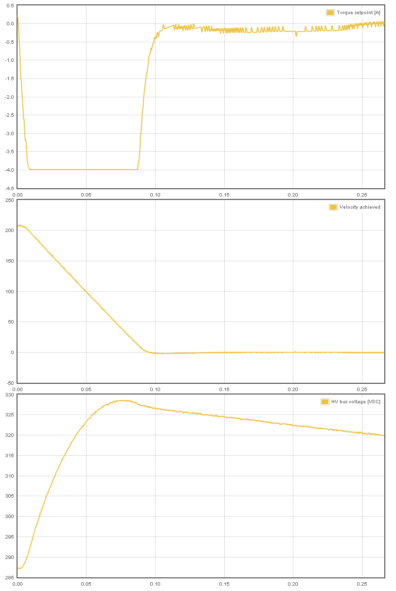
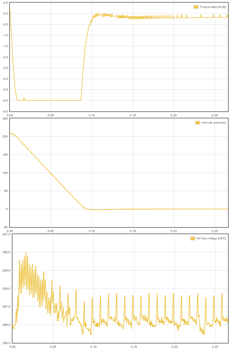
Scenarios where returned energy is causing the rise of HV DC bus voltage:
Voltage generation during deceleration of motor (motor current is negative, current is pumped to HV DC bus causing a 40 VDC rise).
Voltage generation during deceleration of motor (motor current is negative, current is pumped to HV DC bus). However, in this case drive is equipped with regenerative resistor and tightly set Over voltage fault threshold parameter which prevents the significant voltage rise (only 5 VDC rise)
Servo drive with motor can act two ways: energy supply and energy generator. The generator behavior occurs during decelerations and this causes current flow from motor to drive power supply capacitors. If that generated energy is not absorbed anywhere, the voltage of capacitors will rise above overvoltage threshold and trigger an software clearable overvoltage fault.
Scenarios where returned energy is causing the rise of HV DC bus voltage:
- Deceleration of motor speed when there is significant amount of energy stored in mechanical motion (rotating inertia or moving mass). This typically occurs with spindles and linear axes.
- Sudden reversal of torque setpoint. This can generate voltage spike even when motor is standing still. This typically occurs in high bandwidth torque control applications (such as Force Feedback system (FFB)). These spikes are very short and an added capacitor to HV DC bus and/or low resistance regenerative resistor can provide a solution.
Voltage generation during deceleration of motor (motor current is negative, current is pumped to HV DC bus causing a 40 VDC rise).
Voltage generation during deceleration of motor (motor current is negative, current is pumped to HV DC bus). However, in this case drive is equipped with regenerative resistor and tightly set Over voltage fault threshold parameter which prevents the significant voltage rise (only 5 VDC rise)
Monday, May 18, 2020
Collaborativ Robotics
Important factors
Affordability
Return on investment
Size
Safety
Functionality
scalability
ease of programming/customizing for other purpose
precision
Replaces manual labour in repetitive task
Employee skills
Questions to ask
Affordability
What is your financial budget for the cobot?
Does a cobot exist that can carry out the functions required within budget?
Are financing options available for the cobot?
Is it a lease or robots as a service option?
Return on investment
What payback period can you expect
Is this payback period acceptable in terms of your ongoing financial projections?
Size
What is the size of the cobot under consideration?
In particular, what is the cobot’s height, width, depth and footprint?
Is the working environment sufficiently sized so the cobot can be positioned easily?
Will the cobot move around in the workplace? If so, is there enough room for it to comfortably move around in an unimpeded manner?
Safety
Are you sure the cobot can operate in a safely in the allocated workspace?
Have you carried out a health, safety, and risk assessment on the likely impact for staff of introducing a cobot to the workplace?
What is the safety record of the cobot under consideration?
If staff is expected to directly interact with the cobot - have you carried out an ergonomic assessment?
Does the cobot manufacturer or integrator offer safety training? If not, is third-party safety training available?
If you plan on moving the cobot within the workplace, can you do another risk assessment every time?
Functionality
What operations will the cobot be used for? Assembly? Pick-and-place? Machine tending? Human assistance?
Will the cobot be expected to perform a single or multiple functions?
Is the cobot under consideration capable of carrying out all functions necessary? Or will more than one type of cobot be necessary?
Can the cobot manufacturer adapt the cobot to your specific functional requirements?
How easy is it to program the cobot?
Employee skills
Does existing staff have the skills necessary to undertake programming and operational duties for cobots?
Does the manufacturer or dealer offer or provide any sort of staff training?
Is training software (or other information) available?
Affordability
Return on investment
Size
Safety
- Industrial robot - work without a safety fence
- Kukua iiwa - joint torque sensors detect contact immediately and reduces its level of force and speed instantly. position and compliance control enables it to handle delicate components without creating crushing and shearing hazards
- Festo Bionic Cobot - Adjustable level of rigidity/force potential
Functionality
- Atria Innovation - interfaces with cameras that can “automatically adapt themselves to most variations of manufacturing processes.”
scalability
ease of programming/customizing for other purpose
- kuka iiwa - indicate the desired position and it will remember the coordinates of the path point. Controller simplifies the quick start-up of coplex activity
precision
- kuka iiwa - axis-specific torque accuracy of ±2% of the maximum torque
Replaces manual labour in repetitive task
Employee skills
Questions to ask
Affordability
What is your financial budget for the cobot?
Does a cobot exist that can carry out the functions required within budget?
Are financing options available for the cobot?
Is it a lease or robots as a service option?
Return on investment
What payback period can you expect
Is this payback period acceptable in terms of your ongoing financial projections?
Size
What is the size of the cobot under consideration?
In particular, what is the cobot’s height, width, depth and footprint?
Is the working environment sufficiently sized so the cobot can be positioned easily?
Will the cobot move around in the workplace? If so, is there enough room for it to comfortably move around in an unimpeded manner?
Safety
Are you sure the cobot can operate in a safely in the allocated workspace?
Have you carried out a health, safety, and risk assessment on the likely impact for staff of introducing a cobot to the workplace?
What is the safety record of the cobot under consideration?
If staff is expected to directly interact with the cobot - have you carried out an ergonomic assessment?
Does the cobot manufacturer or integrator offer safety training? If not, is third-party safety training available?
If you plan on moving the cobot within the workplace, can you do another risk assessment every time?
Functionality
What operations will the cobot be used for? Assembly? Pick-and-place? Machine tending? Human assistance?
Will the cobot be expected to perform a single or multiple functions?
Is the cobot under consideration capable of carrying out all functions necessary? Or will more than one type of cobot be necessary?
Can the cobot manufacturer adapt the cobot to your specific functional requirements?
How easy is it to program the cobot?
Employee skills
Does existing staff have the skills necessary to undertake programming and operational duties for cobots?
Does the manufacturer or dealer offer or provide any sort of staff training?
Is training software (or other information) available?
Sunday, May 10, 2020
Compliance in industrial robots
Passive compliance is set during the setup of the robotic cell and continuously runs in the background to fulfill its safety role (Eg. Torque limitation device on the end effector or a torque limitation on the joints). It can also be a form of collision detector that prevents collisions from occurring or prevents them from being harmful. These compliance devices are for safety purposes and are important when human-robot collaboration are intended.
Example:
Credits to https://blog.robotiq.com/bid/69962/How-Do-Industrial-Robots-Achieve-Compliance
Tuesday, April 7, 2020
Why taking derivative amplifies noise
Did you know?
Taking derivative amplifies noise.
Why?
By differentiating, you remove the low-frequency components
How?
Assume a noisy input signal

Taking derivative using

When?
1) Finding velocity of motor through its quantized signals (Encoder data or A/D converter output)
2) Image processing, where derivatives are used to help detect the edges. While at mean time, this operation would also make the data noisier
Solution?
As 2 point discrete differentiation is bound to produce highly noisy results. try either
0) Smoothing filter (such as linear phase FIR filter) to alleviate the noise, then do the derivatives
1) 5-points stencil (https://en.wikipedia.org/wiki/Five-point_stencil)
2) Generate coefficients (i.e. more points) yourself using derivation of Lagrange polynomials.
3) Wavelet transform and use derivatives of wavelets. Wavelet transform will allow one to discard high-frequency components, theoretically coming from the underlying noise and sampling rate
( https://www.sciencedirect.com/science/article/abs/pii/S0169743903001370 )
Taking derivative amplifies noise.
Why?
By differentiating, you remove the low-frequency components
How?
Assume a noisy input signal

Taking derivative using
diff(inputSig) 
When?
1) Finding velocity of motor through its quantized signals (Encoder data or A/D converter output)
2) Image processing, where derivatives are used to help detect the edges. While at mean time, this operation would also make the data noisier
Solution?
As 2 point discrete differentiation is bound to produce highly noisy results. try either
0) Smoothing filter (such as linear phase FIR filter) to alleviate the noise, then do the derivatives
1) 5-points stencil (https://en.wikipedia.org/wiki/Five-point_stencil)
2) Generate coefficients (i.e. more points) yourself using derivation of Lagrange polynomials.
3) Wavelet transform and use derivatives of wavelets. Wavelet transform will allow one to discard high-frequency components, theoretically coming from the underlying noise and sampling rate
( https://www.sciencedirect.com/science/article/abs/pii/S0169743903001370 )
The boy who was lost in robotics
Today is the first productive day of
Hi to myself, this is my first post.
Have been wanting to start this for the longest time now, to keep track of some of the weird and wonderful knowledge I gain and how I felt along that way.
All so that I come back to review my time here in Biorobotics lab, I can better judge whether had been worthwhile.
Started work around end July, and at this point of time, 8 months have passed
So much time, yet haven't begun to write any post, just cause couldn't bring myself to do so.
Why?
Because I am fundamentally lazy.
But since the whole (essentially a lockdown, but allegedly not a lockdown) "circuit breaker" started. there has been much spare time for me to do this.
So....let's go.
Subscribe to:
Posts (Atom)